I ran into a few unexpected problems and also made a little bit of progress.
First, on the JDM programmer, I asked some questions and got a few answers on the Usbpicprog Sourceforge forums. The guy who answered said that he could not get his JDM to work at all, also that it could not detect his PIC at all. This is exactly what I experienced as well. I had another look and realized that the CTS line of the RS232 port will never be pulled below 0V by this circuit, thus the computer cannot read any information from the PIC. It also seems that the ciruit I referred to at http://www.jdm.homepage.dk/newpics.htm is actually called the JDM2. I'm not exactly sure, but I think that makes this one the JDM1. Maybe it is better to build that one. Maybe the best position to be in is to have somebody else who can program in the first boot loader for you!
Secondly, I am really having problems getting into programming this PIC. It seems a lot more diffucult than I expected. The admins of the usbpicprog project seem to use Linux only, using Piklab to drive the MPLAB C18 compiler. It took me a long time to find out that some command line utilities of Piklab runs on Windows, but not the main GUI application you need. So I downloaded the MPLAB IDE and I'm trying to set up a project with that. I finally succeeded to the point that it builds, but the hex file I'm getting looks a lot different from the one distributed by the usbpicprog project. There is a lot I don't understand, I'll just have to read, read read!
I also continued working on my usbpicprog veroboard a little bit. I fitted the 3 LED's. Only after started I discovered that there is now a Hardware version 3, so I must be sure to work from this diagram from now on. I did not see a parts list (suppose it must be somewhere so I made it like this:
LED1 = Red
LED2 = Green
LED3 = Yellow
I found that LED1 comes on when you remove the one jumper to make it boot in boot mode. The new circuit says 470 ohm resistors. I did not have, so I used 560 ohms, the LED's are bright enough and it saves milliamps!
Thursday, October 29, 2009
Thursday, October 22, 2009
Usbpicprog Howto (1) - Building a JDM Programmer
It seems the JDM programmer was designed and is named after Jens Dyekjær Madsen, diagram at http://www.jdm.homepage.dk/newpics.htm. I have however built the one given at http://usbpicprog.org looking like this:
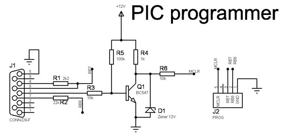
If you look at the original JDM schematic, you will see it is totally different. I think the original one has the disadvantage that is uses positive and negative voltages from the RS232 port to get a total of 12V. This means that the Vss of the PIC being programmed will not be at 0V w.r.t. the PC, which means it should be floating and not connected to earth in any way. This may be problematic for a programmer claiming to be an In Circuit Programmer. The other disadvantages of that programmer is that it needs 2 Zener diodes which could be more difficult to obtain than the bunch of resistors in this one. This one on the other hand has the disadvantage that it needs an external 12V supply. I did not have a BC547 transistor. I had a BC517 which looked like it is a Darlington. I tried that first, thinking that when a Darlington switches on, it swithses on harder. It would not work, I think probably because the biasing with the resistors should be different for a Darlington. I ended up using an old NPN transistor without a proper number on it which worked. So it seems it is not very sensitive to the type of transistor, as long as it is an NPN switching transistor and not a Darlington. Finally I was able to program the boot loader into my PIC 16F2550, the only problem is that it does not read back from the PIC. I am still trying to find out why.
Below is my JDM programmer from the top. Note that I soldered the 5 pins on the 9-pin D connector which is in one row to 5 tracks at the bottom of the verobord. Note that as I have build it, the numbering of pins 1-5 on the connector is the opposit as the numbering of the ribbon calble on the other side. Aslo note that you need a female connector, as the RS232 connector on a PC is male. I used an old 10-way ribbon cable from a very old RS232 card. As you can see, I soldered it on the JDM board, it plugs int on the header of the Usbpicprog board. the red wire and the black/white wires are for the 12 V supply. I had a 6.5 Ah battery that dit not work properly for my house alarm any more, but still measured over 12V, that worked for me.

Here is the veroboard seen from the bottom. Ir you really want to, you might be able to copy mine. I do not like planning these things ahead. I just start building, cutting tracks as needed. (You know of course that you use a drill bit turned by hand to cut the tracks? If you have a handle in which you can mount the drill bit, even better.) Working in this unplanned fassion does not allways work out - can you see I had to run one wiret through a cut out hole!

Winpic800 installation:
I used an old PC running Windows 2000. (Better to use an old PC in case you blow up the RS232 port - however that is not likely to happen.) Every time I installed Winpic800, installation of it's IO driver failed. I found somewhere that they said you must install it manually, but not how. I don't remember the exact procedure now, but start from the hardware wizard or somthing device, install a device manually and say you want to install it manually. You will find the .inf file of the driver somewhere in c:\Program Files where Winpic800 is installed. If you can't figure it out, let me know, I'll try to help.
Testing:
If you have your Usbpicprog board already built, do not plug the PIC in it's socket yet - I assume you are using a socket!.
Do not plug the JDM to the PC yet or connect the 12V supply. Use your multimeter on kOhms scales. Measure from pin 4 of the 9-pin connector to pin 28 of the PIC socket. You should read the 2k2 resistor. Then measure from pin 7 of the connector to pin 27 of the PIC socket, you should read the 22k resistor.
Plug the JDM to P2 on the Usbpicprog the JDM to the serial port and connect your 12V supply. Now use your multimeter to measure between ground and pin 1 of the PIC socket. Now run Winpic800, be sure to select the correct COM port you are using. Now tell Winpic800 to program the PIC. If you can manage to sometimes see 0V or very close to 0 V and at other times 12V you could be reasonably sure that your transistor is switching OK.
Now you should be ready, disconnect the 12V and RS232. Plug in the PIC and after connecting everything again, you can program your PIC. You can use a 9-pin D straight cable to connect the JDM to the port.
Final Note:
In Winpic800 I had to select to invert MCLR. You might also need to tell Winpic800 to first erase the PIC before you can program it correctly.
Tuesday, October 20, 2009
The Usbpicprog Project
When I heard a year or so ago that some of MicroChip's PIC controllers now support a USB connection. I was interested, especially since I have worked with some of the PIC's a number of years ago, notably the 16C84. Starting to search for information on the internet, I found the usbpicprog project on http://sourceforge.net/projects/usbpicprog. The web site of the project is at http://usbpicprog.org/
I don't particularly like pc board design and making, and have not really aquired those skills. I do like embedded programming and electronic design at schematic level. So I like to build things up stepwise on veroboard. Below is my usbpicprog, not complete, but doing the most important thing already - talking to the PC via USB! Actually, my interest in the project is not really for it as a PIC programmer (yes, as a side product), but to learn how to communicate with a device via usb.

I don't particularly like pc board design and making, and have not really aquired those skills. I do like embedded programming and electronic design at schematic level. So I like to build things up stepwise on veroboard. Below is my usbpicprog, not complete, but doing the most important thing already - talking to the PC via USB! Actually, my interest in the project is not really for it as a PIC programmer (yes, as a side product), but to learn how to communicate with a device via usb.

usbpicprog on veroboard with bare necesities for usb comms
In general, the documentation on http://usbpicprog.org is very good, but as always with documentation written by programmers/designers, what is obvious to them is not always obvious to the reader. (Or put it down to me not reading properly!) The first thing not completely clear to me was, what the usbpigprog can do and what is the purpose of the different headers. The way I see it is:
1. USB Comms and self programming: The PIC can communicate with the software on the PC, you can program the firmware in the PIC, using only the 5V supplied via the USB cable, the voltage pump is not required for that.
2. Programming Header P1: The usbpicprog is an in ciruit PIC programmer, thus it can program another PIC on another board via Header P1. To do this, you need 12V, that is what the voltage pump is for. So if you just want to use the knowledge to build some other usb device, not a programmer, you might not need P1 or the voltage pump.
3. Self Programming Header P2: Note the firmware programming in (1) assumes the boot loader is already loaded in the 18F2550. If not, you need Header P2 and something like a JDM programmer to program in the boot loader. Otherwise, if say you have another PIC programmer in which you can plug the 18F2550 to program the boot loader, you might ommit Header P2, but note that you will then have to tie Pin 1 of the PIC Vpp to Vdd (5V) and put at least 2 pins for a jumper between ground and PGC_SELF, pin 27 of the PIC, to select between boot mode and normal mode.
I will try to explain here, in more details, everything I needed to do for the things I have already achieved and will hopefully achieve in future. I think he steps I take will be
- Building the JDM programmer, circuit shown on http://usbpicprog.org
- Building the bare necessities of the usbpicprog.
- Programming the boot loader using Winpic800.
- Driver installation and software installation on PC.
- Firmware programming.
- Completing the usbpicprog board.
- Building an external PIC board to use P1, fully testing the usbpicprog.
Subscribe to:
Posts (Atom)