If you look at the original JDM schematic, you will see it is totally different. I think the original one has the disadvantage that is uses positive and negative voltages from the RS232 port to get a total of 12V. This means that the Vss of the PIC being programmed will not be at 0V w.r.t. the PC, which means it should be floating and not connected to earth in any way. This may be problematic for a programmer claiming to be an In Circuit Programmer. The other disadvantages of that programmer is that it needs 2 Zener diodes which could be more difficult to obtain than the bunch of resistors in this one. This one on the other hand has the disadvantage that it needs an external 12V supply. I did not have a BC547 transistor. I had a BC517 which looked like it is a Darlington. I tried that first, thinking that when a Darlington switches on, it swithses on harder. It would not work, I think probably because the biasing with the resistors should be different for a Darlington. I ended up using an old NPN transistor without a proper number on it which worked. So it seems it is not very sensitive to the type of transistor, as long as it is an NPN switching transistor and not a Darlington. Finally I was able to program the boot loader into my PIC 16F2550, the only problem is that it does not read back from the PIC. I am still trying to find out why.
Below is my JDM programmer from the top. Note that I soldered the 5 pins on the 9-pin D connector which is in one row to 5 tracks at the bottom of the verobord. Note that as I have build it, the numbering of pins 1-5 on the connector is the opposit as the numbering of the ribbon calble on the other side. Aslo note that you need a female connector, as the RS232 connector on a PC is male. I used an old 10-way ribbon cable from a very old RS232 card. As you can see, I soldered it on the JDM board, it plugs int on the header of the Usbpicprog board. the red wire and the black/white wires are for the 12 V supply. I had a 6.5 Ah battery that dit not work properly for my house alarm any more, but still measured over 12V, that worked for me.

Here is the veroboard seen from the bottom. Ir you really want to, you might be able to copy mine. I do not like planning these things ahead. I just start building, cutting tracks as needed. (You know of course that you use a drill bit turned by hand to cut the tracks? If you have a handle in which you can mount the drill bit, even better.) Working in this unplanned fassion does not allways work out - can you see I had to run one wiret through a cut out hole!

Winpic800 installation:
I used an old PC running Windows 2000. (Better to use an old PC in case you blow up the RS232 port - however that is not likely to happen.) Every time I installed Winpic800, installation of it's IO driver failed. I found somewhere that they said you must install it manually, but not how. I don't remember the exact procedure now, but start from the hardware wizard or somthing device, install a device manually and say you want to install it manually. You will find the .inf file of the driver somewhere in c:\Program Files where Winpic800 is installed. If you can't figure it out, let me know, I'll try to help.
Testing:
If you have your Usbpicprog board already built, do not plug the PIC in it's socket yet - I assume you are using a socket!.
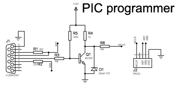
Do not plug the JDM to the PC yet or connect the 12V supply. Use your multimeter on kOhms scales. Measure from pin 4 of the 9-pin connector to pin 28 of the PIC socket. You should read the 2k2 resistor. Then measure from pin 7 of the connector to pin 27 of the PIC socket, you should read the 22k resistor.
Plug the JDM to P2 on the Usbpicprog the JDM to the serial port and connect your 12V supply. Now use your multimeter to measure between ground and pin 1 of the PIC socket. Now run Winpic800, be sure to select the correct COM port you are using. Now tell Winpic800 to program the PIC. If you can manage to sometimes see 0V or very close to 0 V and at other times 12V you could be reasonably sure that your transistor is switching OK.
Now you should be ready, disconnect the 12V and RS232. Plug in the PIC and after connecting everything again, you can program your PIC. You can use a 9-pin D straight cable to connect the JDM to the port.
Final Note:
In Winpic800 I had to select to invert MCLR. You might also need to tell Winpic800 to first erase the PIC before you can program it correctly.
Harrah's Cherokee Casino Resort - Mapyro
ReplyDeleteFind Harrah's Cherokee Casino 울산광역 출장안마 Resort (North 김포 출장안마 Carolina) location 광주광역 출장마사지 in North 남원 출장샵 Carolina, 충주 출장안마 revenue, industry and